RF measurement for Windows · NanoVNA text protocol

S11 and S21 measurements from a NanoVNA

RF Lab acquires S11 and S21 through a USB serial COM port and displays magnitude, phase, impedance, Smith chart, group delay and TDR views from the same sweep. It uses the NanoVNA text console; devices that require the binary NanoVNA V2 protocol are not supported.

Download information Read the manual

Windows 10/11, 64-bit · COM port (USB CDC) · no VISA runtime

Instrument compatibility

RF Lab expects the text console prompt ch> and the commands info, scan, frequencies, data 0, data 1 and cal off. A COM port or a NanoVNA name alone does not establish compatibility. Firmware response format and sweep limits also matter.

Tested with hardware

NanoVNA-F series unit identified as NanoVNA-F_V2 (referred to as NanoVNA-F3 in this project). Its firmware accepts 11–201 points per scan. Other firmware and hardware revisions need validation.

Text-protocol model families

NanoVNA (classic), NanoVNA-H/H4, NanoVNA-F/F V2/F V3 and LiteVNA 62/64 are documented as text-console families. RF Lab has not been tested on every listed model; compatibility depends on the firmware implementing the commands above.

Not supported

OwOComm NanoVNA V2 (SAA2/SAA2N), V2 Plus/Plus4 and V3 use a different binary protocol. NanoVNA-F V2 and NanoVNA V2 are different product families despite the similar names. Siglent control is not available in the current GUI.

See the compatibility notes before connecting another model.

RF Lab
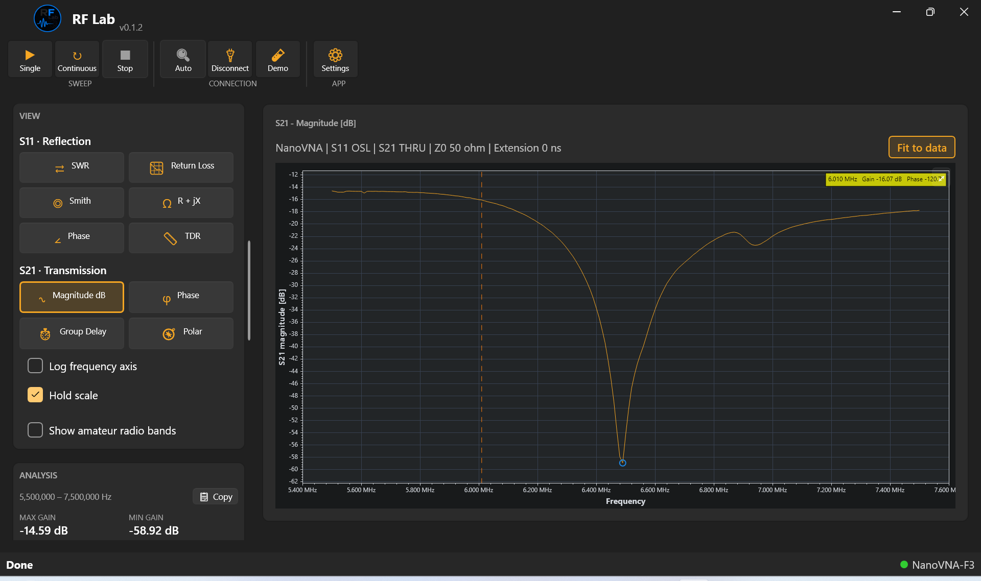
RF Lab S21 transmission measurement of a real RF circuit

S21 measurement. Transmission of a real RF circuit measured with a NanoVNA, shown in dB.

Measurements and views

One sweep contains S11 and S21. Changing the view uses the captured data without another acquisition. A saved memory trace can be shown beside a later measurement.

Full Smith chart

Constant-resistance circles and constant-reactance arcs behind your S11 trace, with Q, parallel R+jX and equivalent L/C values in marker readouts.

OSL calibration

OPEN/SHORT/LOAD corrects S11; an optional THRU provides response correction for S21. Saved calibrations require explicit activation for matching sweep settings and the same physical setup.

Memory & overlay traces

Save a sweep and overlay it against a later one - each trace gets its own color, renamed in place, and skipped from re-saving if nothing changed.

Additional functions

Return Loss, R+jX & S21 Polar

Reflection expressed as Return Loss (dB), impedance as R+jX(Ω) against frequency, or S21 as a vector on a polar plot - the same sweep, three more lenses.

S21 & S11 phase

Phase (°) against frequency for either parameter, alongside the usual gain/magnitude views.

Group Delay

−dφ/dω computed from S21's own unwrapped phase - a phase-linearity check for filters and amplifiers.

TDR / distance to fault

Derived from S11 with a cable velocity factor. Band-pass impulse and low-pass step modes have different frequency-grid requirements; verify distances against a known cable.

Segmented sweep

Up to 16 separate scans are combined into one trace. Each scan must stay within the connected device's point-count limit.

Touchstone import/export

Load a reference .s1p/.s2p file as a memory trace. Export measured S11 as .s1p, or save both measured S11 and S21 in Sweep CSV.

Amateur radio band overlay

Shade the amateur bands that fall inside your current sweep range directly on the chart, scoped to what you're actually viewing.

Demo mode

The ordinary Demo sweep models a series RLC circuit between two 50-ohm ports. S11 and S21 come from the same impedance; no instrument is connected.

Export to MD Visor, CSV or PNG

Save sweep data as CSV, the displayed chart as PNG, or an MD Visor report.
Download and setup

Download information