Measuring a power amplifier
Step by step, from building the load to the last number. Each step says what to set, what you should see, and what to check when you do not. The overview of all devices is on What to measure, the controls are explained in the Manual.
At a glance
What is worth measuring on a power amplifier, with which task and what a good result is; the steps below show how.
| What | Task | Set | Good value |
|---|---|---|---|
| THD+N at 1 W, 1 kHz | THD+N meter | 1000 Hz; raise Level until the bar shows 1 W | 0.01 % good, 0.001 % excellent |
| Power at 1 % THD+N | THD vs level | 1 kHz, From −40 To −6 dBFS, Step 1 dB; Load set | as rated; the bar reads “1 % THD+N at … W” |
| Distortion over the band | THD vs frequency | 20 Hz – 20 kHz, 31 points, level for a few W | a mild rise towards 20 kHz is normal |
| Kind of distortion | THD+N meter → Scope | 1 kHz at a few W, then near clipping | a smooth residual; steps at the zero crossings = crossover distortion (bias too low), spikes at the peaks = clipping |
| Adjusting the quiescent current live | Multitone (or THD+N meter) with RUN | level for a few W; turn the trimmer slowly | the lowest TD+N, and no change when warm |
| S/N | Noise & S/N | S/N against a test tone on, level = rated power; read the A value | 100–120 dB re rated power |
| Frequency response | Gain & phase | −20 dBFS | 20 Hz – 20 kHz ±0.5 dB |
| Crosstalk | Crosstalk | stereo wiring, level for a few W | −60 to −90 dB at 1 kHz |
| Damping factor | Output Z | Load 8 Ω; read without, then with the load resistor (step 7.7) | above 100 (Z below 0.08 Ω) |
| Hum | Spectrum | generator off, input connected | below −100 dBFS at 50/100 Hz |
1. Safety first
- Never connect an amplifier's speaker output straight to the audio interface. 100 W into 8 Ω is 28 V; an interface input takes about 5–8 V. Always through a power load and an attenuator.
- Bridged (BTL) and most class D amplifiers have no grounded output terminal. Connecting the speaker minus to the interface ground shorts half of the output stage. The attenuator below is balanced and never connects the minus to ground.
- Class D amplifiers also need a passive low-pass filter (AES17 type) between the attenuator and the interface, or their switching carrier distorts the reading. Tick AES17 filter (class D) under CONNECTIONS: the band is held to 20 kHz and the filter is listed in the cables and the report; enter its loss (and pad) as the Divider of the output inputs.
- Before the first connection, check with a multimeter that the attenuator output stays below about 3 V RMS at the highest level you will use.
- Set Settings → Generator output limit before you start, and start every measurement at a low level (−40 dBFS).
- Some amplifiers oscillate without a load: always measure into the resistor.
- Power resistors get hot: mount them on a heatsink and keep full-power sweeps short.
2. What you need
| Item | For |
|---|---|
| Audio interface with four inputs and its manufacturer's driver (e.g. MOTU M4) | stereo with a reference per channel; two inputs work one channel at a time |
| Dummy load per channel: two 4 Ω resistors rated for the power (e.g. 100 W, 1 %, in an aluminium case) on a heatsink | replaces the speaker: 8 Ω or 4 Ω |
| Balanced attenuator per channel, switched −22 / −12 / −10 dB (step 3) | brings the speaker voltage down to line level |
| True-RMS multimeter | calibration, measuring the attenuator, checking the power |
| Cables: RCA to the amplifier input with a Y-splitter for the reference; TRS from the attenuator to the interface | wiring |
3. Building the load and the attenuator
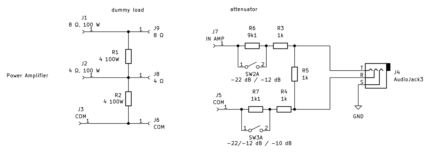
Two blocks per channel, joined by short cables. Dummy load: the amplifier's plus to J1 (8 Ω) or J2 (4 Ω), its minus to J3 (COM); each has a second post for the attenuator (J9, J8, J6). Attenuator: J7 (IN AMP) and J5 (COM) take the voltage, the output is read balanced across R5. The jack's sleeve goes to the interface ground only, never to COM, so a bridged (BTL) amplifier is safe too.
| SW2A | SW3A | Attenuation | 3 V at the interface at |
|---|---|---|---|
| open | open | 1 k / 13.2 k = −22.4 dB | 40 V: 196 W into 8 Ω – above the load's rating |
| closed | open | 1 k / 4.1 k = −12.3 dB | 12.3 V: 19 W into 8 Ω, 38 W into 4 Ω |
| closed | closed | 1 k / 3 k = −9.5 dB | 9 V: 10 W into 8 Ω, 20 W into 4 Ω |
- Connect the attenuator to J9 (8 Ω) and J6 (COM) – it then reads the load voltage with the amplifier on either post: on J2 no current flows in R1, so J9 carries the same voltage. Taken from J8 (4 Ω) while the amplifier is on J1, it would read only half the voltage – every level 6 dB low and the power a quarter.
- Start with −22 dB; switch to −12 or −10 dB only for low power, where the stronger signal lifts the reading above the interface's noise. Never switch the attenuator during a measurement.
- The interface input lies across R5 and lowers the attenuation a little below the calculated value – hence the measurement below.
- The load: in series (J1) the two resistors share the power, 200 W in all; on J2 R2 alone takes it, 100 W.
- Output Z (step 7.7): for the reading without a load, take the amplifier off J1/J2 and connect the attenuator straight to the amplifier's output; for the loaded reading, put the amplifier back on the load with the attenuator on J9/J6.
Measure the attenuation once for each setting you use: play a 1 kHz tone into the attenuator, read the voltage before and after it with the multimeter, and note 20·log10(Vafter / Vbefore) – you enter this value in AudioLab as the Divider of the output inputs. Use wire of at least 1.5 mm² for the power connections.
4. Wiring
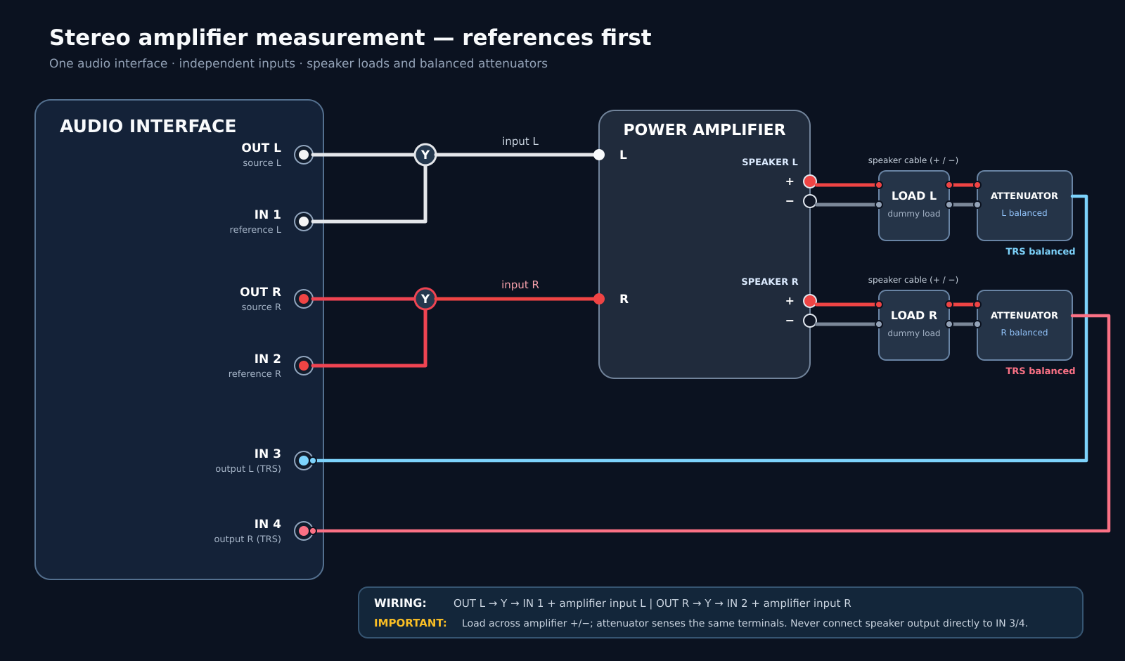
- This is Wiring = Stereo, references first: the amplifier's outputs go to inputs 3–4, which on many interfaces (an M4: rear line inputs) are the better ones for distortion and noise.
- Take the reference at the amplifier input with the Y-splitter, not at the interface.
- On a MOTU M4 use the rear RCA outputs 3–4 (they mirror LINE OUT 3–4, fixed level) and set Settings → Audio → Generator outputs = Outputs 3–4. Never plug a TS (mono) jack into the M4's quarter-inch outputs.
- For the frequency response (step 7.4) you may switch to Wiring = Stereo (reference and output of each channel on the same kind of input); see Wiring and the reference in detail.
5. Setting up AudioLab
- CONNECTIONS: Audio interface = your interface, Wiring = Stereo, references first, On the device output = 8 Ω (or 4 Ω, as wired; it starts at Nothing (open) every time AudioLab opens).
- Calibration (once per interface): CALIBRATION → Calibrate…, an interface output straight to each input, multimeter across the same connection – see Calibration.
- Divider: in the calibration summary enter the measured attenuation (e.g. 20.3) in Divider [dB] for IN 3 and IN 4. AudioLab then shows the voltage on the load, and with the load set, the power in W.
- Settings → Chart → Show levels in volts (dBV) on.
- Settings → Generator output limit: a level the amplifier cannot take beyond its rating.
- Amplifier volume (if it has one) at maximum or a fixed position; note it.
- Power in W: in CONNECTIONS → On the device output choose the load that is connected right now (speaker 2/4/8/16 Ω, headphones 16/32/300/600 Ω). AudioLab switches nothing – the choice only says what is on the output; at start it is always Nothing (open). With the output inputs calibrated (and the divider entered), the Level meter and THD+N meter also show the power into the load (P = V² / R, from pW to W), and THD vs level runs over output power, with the power at 1 % THD+N – the usual rating – in the bar.
- Measured loads (optional, the Measured… button next to On the device output): the actual resistance of each load, for L and R separately, and the path resistance of L and R – cable and contacts from the amplifier output to the load and back. Measure with an ohmmeter, ideally 4-wire; for the path, short the cable's plug at the amplifier end and add tip → top of the load and sleeve → common ground. An empty field means the nominal value (path 0). Power in W then uses the actual R of each channel, and Output Z uses it and subtracts the path. The values belong to the load box and its cable, not to the interface: they do not depend on the calibration, apply to every interface, are shown under On the device output and listed in the export header. A load outside half to twice its nominal value, or a path outside 0–10 Ω, is not stored. Copy in the dialog copies every entry.
6. Know the floor first
Before the amplifier, connect an interface output straight to inputs 3 and 4 (no amplifier) and run THD+N meter and Noise & S/N – or simply watch the reference rows during every measurement. That is the best the interface can show. Optionally Keep it and pin it in TRACES, so it shows under later measurements of the same task.
What the attenuator does to the floor: it brings the signal down by 22 dB, the interface noise stays. With an interface noise of about −114 dBFS and 1 W into 8 Ω (2.83 V on the load, 0.21 V after −22.4 dB, about −31 dBFS on a 7.5 V input), THD+N cannot read better than about −83 dB (0.007 %). At 10 W it is about −93 dB (0.002 %) – or −103 dB with the attenuator on −12 dB, which still keeps the interface input below 3 V. A better amplifier reads at this limit – read its THD (harmonics only, which sit far below the noise in their own bins) or measure at higher power.
7. Measurements
7.1 THD+N at 1 W, 1 kHz
- MEASUREMENT → THD+N meter; SIGNAL: 1000 Hz, Level −40 dBFS; ANALYSIS: Unweighted; Settings → Analysis: Band up to 20000, Up to harmonic 10, FFT 65536, Blackman-Harris, Averages 4.
- RUN, raise Level step by step until the bar shows 1 W (2.83 V on 8 Ω).
- Read THD+N and THD of both channels; tick Details for the harmonics.
Good: THD+N 0.01 %, excellent 0.001 % (see the floor above – at 1 W read THD). Check: multimeter on the load posts shows 2.83 V (= 1 W into 8 Ω) within a few percent.
7.2 Power at 1 % THD+N
- MEASUREMENT → THD vs level; SIGNAL: 1000 Hz, From −40, To about 6 dB above the 1 W level, Step 1 dB.
- SINGLE. With the load set and the outputs calibrated, the axis runs in W and the bar reads 1 % THD+N at … W.
- If it reads not reached, raise To (within the generator limit) and repeat.
Good: close to the rated power (often a little below with a weak mains or 1 % resistors). The curve falls with level, then rises sharply at clipping – that knee is the usable power.
7.3 Distortion over the band
THD vs frequency, 20 Hz – 20 kHz, 31 points, level for a few W, SINGLE. Good: flat, a mild rise towards 20 kHz is normal (less feedback at high frequencies). Above 10 kHz THD reads “—” (harmonics above 20 kHz), THD+N stays valid.
7.4 Frequency response
Wiring = Stereo (optional, see step 4). Gain & phase, −20 dBFS, RUN. Good: 20 Hz – 20 kHz ±0.5 dB; with volts on the gain is the amplifier's voltage gain (typically +26 to +32 dB). With both channels the bar adds L−R.
7.5 Noise and S/N
Noise & S/N, S/N against a test tone on, tone at the rated power level (or 1 W for a comparison), SINGLE. Read the A-weighted value. Good: 100–120 dB re rated power. interface limit = the amplifier is at least that quiet.
7.6 Crosstalk
Crosstalk, level for a few W, 20 Hz – 20 kHz, SINGLE. Good: −60 to −90 dB at 1 kHz, rising towards 20 kHz.
7.7 Damping factor (output impedance)
Output Z compares the output voltage without and with the load. Without the load, the attenuator is connected straight to the amplifier's output (J7, J5) and the dummy load is off; with it, the amplifier is back on J1 and the attenuator on J9/J6 (step 3).
- Output Z, 1 kHz, low level (a few hundred mV on the output). No load (amplifier to the attenuator only), On the device output = Nothing (open), RUN.
- Amplifier on J1 (8 Ω), attenuator on J9/J6, On the device output = 8 Ω.
Good: damping factor above 100 (Z below 0.08 Ω); a modern amplifier often reads Z below … – too stiff to resolve with an 8 Ω load. Some amplifiers do not like running without a load – keep the level low and the open reading short.
7.8 Hum
Spectrum, Play test signal off, amplifier input connected. Good: 50/100 Hz below −100 dBFS.
8. Is the result valid?
| Check | What it tells |
|---|---|
| Output well above the reference (THD+N, IMD, noise) | the number is the amplifier's. Output close to the reference = you measure the interface; the amplifier is at least that good. |
| interface limit in Noise & S/N | the amplifier is quieter than the interface can show |
| Watts in AudioLab = V²/R from the multimeter on the load | calibration and divider are right |
| No CLIPPING, no Input clipping detected | the interface input is not overloaded (otherwise switch the attenuator to −22 dB, both switches open) |
| Fundamental not “No test signal” | the signal reaches the inputs the wiring expects (Inputs line above the chart) |
| Both channels similar | a large difference points to a fault in one channel (or one cable) |
9. When it does not fit
| Symptom | Likely cause |
|---|---|
| THD+N far worse than expected, spectrum full of lines at 50/100/150 Hz | ground loop: laptop charger (measure on battery; a desktop computer through a USB 2.0 High Speed isolator), mains of the amplifier and the PC on different sockets |
| Higher noise than before | laptop charger connected, multimeter leads left on, loose cables |
| Strange spikes high in the spectrum, unstable readings | the amplifier oscillates (no load, long speaker wires) or a class D carrier without the AES17 filter |
| Output reads “No test signal” | cable not fully inserted, wrong Wiring or Generator outputs |
| Power in W clearly off | divider value not entered or not measured, Load not matching the post used |
| Level drops when more inputs are connected | a TS jack in a balanced quarter-inch output of the interface – use TRS or the RCA outputs |